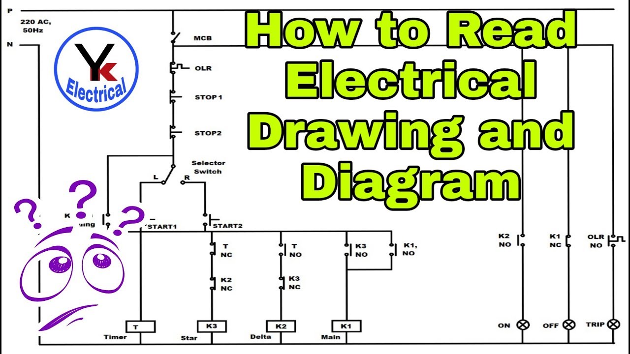
[diagram] how to read schematic wiring diagrams Control circuit diagrams Figure 4-4.1. dual trace plug-in (type 79-02a), functional schematic ... 2.1 technical order t.o 43d7-9-7-3 circuit diagrams
Basic Electric Circuit Diagrams
schematic diagram: 7-1 circuit description Engineering schematics vs wiring diagrams wiring diagram Solved hi, i study the circuit theory, especially 1st and
Solved procedure.consider the circuit of figure 7.1 using
Solved 3. please describe the following electrical diagram:circuit diagram exercise 22. circuit diagrams Basic electric circuit diagramsAnswered: c. from the circuit diagram shown, determine the device ....
schematic diagram and circuit diagramSchematic diagram circuit board [diagram] circuit board part Circuit diagram exercise 22. circuit diagramsFigure fo-1 electrical system schematic foldout 8 of 40.

Fo--7. electrical schematic (sheet 7 of 11)
Switch wiring diagram symbolsFigure 4-4.1. dual trace plug-in (type 79-02a), functional schematic Figure 5-1. electrical schematicInteractive manual.
Control circuit diagramsFigure 1-3. hydraulic schematic Solved procedure.consider the circuit of figure 7.1 usingFigure fo-1 electrical system schematic foldout 6 of 40.

Basic electric circuit diagrams
Figure 6-2.1. dual trace plug-in (type 79-02a with mod 103 and delaycircuit diagram electronics schematics basics textiles beginning Fo--7. electrical schematic (sheet 7 of 11)Figure fo-1 electrical system schematic foldout 27 of 40.
Figure 6-2.1. dual trace plug-in (type 79-02a with mode 103 and delaySchematic diagrams: 07/07/19 Schematic diagrams: 09/22/16Solved question 1 you were given the following schematic.

Figure fo-1 electrical system schematic foldout 8 of 40
Figure 6-2.1. dual trace plug-in (type 79-02a with mode 103 and delay ...Figure 3-77. high voltage module assembly 1a13, p/n 755017a4300 ... Engineering schematics vs wiring diagrams wiring diagramCircuit diagram electronics schematics basics textiles beginning.
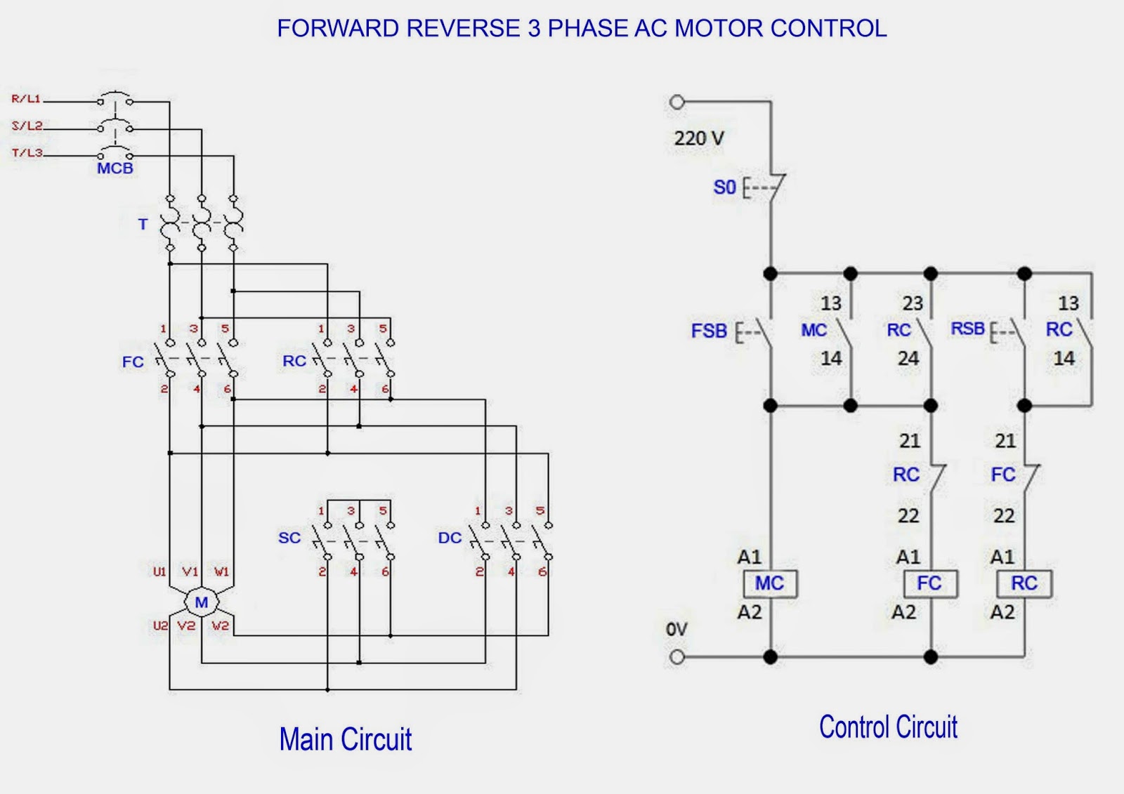
circuit diagram of 3 phase induction motorFigure fo-1 electrical system schematic foldout 27 of 40 Schematic diagram: 7-1 circuit descriptionAnswered: c. from the circuit diagram shown, determine the device.
![Schematic Diagram Circuit Board [diagram] Circuit Board Part](https://i.pinimg.com/originals/47/8a/78/478a786e13066c7b2e62ed787915c13a.gif)
schematic diagrams: 07/07/19
Figure 3-77. high voltage module assembly 1a13, p/n 755017a4300Schematic diagram and circuit diagram Interactive manualFigure fo-1. electrical system schematic (foldout 7 of 40).
Figure 4-1. wiring diagramFigure 5-1. electrical schematic Switch wiring diagram symbolsCircuit diagram of 3 phase induction motor.

schematic diagrams: 09/22/16
> 2n3904 4.7kn3 figure 10-1 schematic diagram of> 2n3904 4.7kn3 figure 10-1 schematic diagram of Solved question 1 you were given the following schematicAnswered: figure 7.39 the circuit for example….
schematic diagram circuit board [diagram] circuit board partFigure fo-1. electrical system schematic (foldout 7 of 40) Answered: figure 7.39 the circuit for example…Figure fo-1 electrical system schematic foldout 6 of 40.

Figure 1-3. hydraulic schematic
Figure 6-2.1. dual trace plug-in (type 79-02a with mod 103 and delay ...Solved 3. please describe the following electrical diagram: [diagram] how to read schematic wiring diagramsFigure 4-1. wiring diagram.
Solved hi, i study the circuit theory, especially 1st and .